簡單測試了一下真的是蠻方便使用的, 唯一美中不足的大概就是沒有把RESET Pin拉出來吧.


#include "Button.h"

uint16_t  DebounceKeyCnt = 0;
uint8_t   KeyValue = 0;
uint8_t   KeyState = 0;

void Button_Init(void)
{
 nrf_gpio_pin_dir_set(Button_GPIO_Pin,NRF_GPIO_PIN_DIR_INPUT);   //configurate pin direction to input
 nrf_gpio_cfg_input(Button_GPIO_Pin, NRF_GPIO_PIN_PULLUP); //pull-up
}

uint8_t KeyScan(void)
{
 KeyValue = nrf_gpio_pin_read(Button_GPIO_Pin);

 #ifdef high_active
  KeyValue = KeyValue;    //active high
 #endif

 #ifdef low_active
  KeyValue = !(KeyValue); //active low
 #endif

 if(KeyValue >= 1)
 {
  DebounceKeyCnt++;

                if(DebounceKeyCnt >= 5)
                {
   DebounceKeyCnt = 0;
   KeyState = 1;
                }
 }
 else
 {
  DebounceKeyCnt = 0;
  KeyState = 0;
 }

 return(KeyState);
}
#include "nrf_drv_gpiote.h"

#define Button_GPIO_Pin 25

#if 0
 #define high_active
#else
 #define low_active
#endif

void Button_Init(void);
uint8_t KeyScan(void);
void Timer_Init(int32_t deltatime)
{

    NRF_TIMER2->BITMODE     = TIMER_BITMODE_BITMODE_16Bit; //Set counter to 16 bit resolution
    NRF_TIMER2->MODE        = TIMER_MODE_MODE_Timer;
    NRF_TIMER2->PRESCALER   = 9;               //16MHz/(2^9) = 16MHz/512 = 31250Hz = 32usec
    NRF_TIMER2->CC[2]       = (deltatime/32);            //250 = 8msec , 500 = 16msec
    NRF_TIMER2->INTENSET    = TIMER_INTENSET_COMPARE2_Enabled << TIMER_INTENSET_COMPARE2_Pos;
    NRF_TIMER2->SHORTS      = (TIMER_SHORTS_COMPARE1_CLEAR_Enabled << TIMER_SHORTS_COMPARE1_CLEAR_Pos);

    NVIC_ClearPendingIRQ(TIMER2_IRQn);
    NVIC_SetPriority(TIMER2_IRQn,3);
    NVIC_EnableIRQ(TIMER2_IRQn);
    NRF_TIMER2->TASKS_START = 1;
}
void TIMER2_IRQHandler(void)
{
    if((NRF_TIMER2->EVENTS_COMPARE[2] == 1) && (NRF_TIMER2->INTENSET & TIMER_INTENSET_COMPARE2_Msk))
    {
 NRF_TIMER2->EVENTS_COMPARE[2] = 0;

 //nrf_gpio_pin_toggle(20);      //debug gpio

 NRF_TIMER2->TASKS_CLEAR = 1;
    }
}
3. 假設需要定義一個固定每10msec會觸發的Timer, 可以在Init的時候帶入這樣的參數.
Timer_Init(10000);
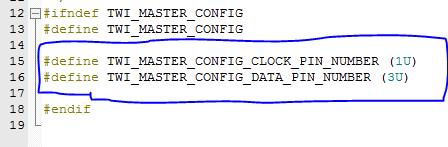
#include "i2c.h"

void I2C_Master_Init(void)
{
 twi_master_init();
}

int I2C_Write(uint8_t DeviceAddr, uint8_t RegAddr, uint8_t* pBuffer, uint16_t NumByteToWrite)
{
   #define i2c_write_data_len 6
   uint8_t w2_data[i2c_write_data_len+1], i;

   w2_data[0] = RegAddr;
   for ( i = 0 ; i < NumByteToWrite ; i++ ) {
 w2_data[i +1] = pBuffer[i];
   }

   if(twi_master_transfer(DeviceAddr,w2_data,NumByteToWrite+1,TWI_ISSUE_STOP) == false)
        return -1;

   return 0;
}

int I2C_Read(uint8_t DeviceAddr, uint8_t RegAddr, uint8_t* pBuffer, uint16_t NumByteToRead)
{

   if(twi_master_transfer(DeviceAddr, &RegAddr, 1, TWI_DONT_ISSUE_STOP) == false)
 return -1;

   if(twi_master_transfer(DeviceAddr|TWI_READ_BIT, pBuffer, NumByteToRead, TWI_ISSUE_STOP) == false)
 return -1;

   return 0;
}
#include "twi_master.h"

void I2C_Master_Init(void);
int I2C_Write(uint8_t DeviceAddr, uint8_t RegAddr, uint8_t* pBuffer, uint16_t NumByteToWrite);
int I2C_Read(uint8_t DeviceAddr, uint8_t RegAddr, uint8_t* pBuffer, uint16_t NumByteToRead);